Understanding Incremental Rotary Encoders
2025-03-29
Table of Contents
- Types of Rotary Encoders
- Absolute Encoders
- Incremental Encoders
- How Incremental Encoders Work
- Signal Representation
- Quadrature Outputs
- Quadrature Encoding Table
- Resolution of an Incremental Encoder
- ESP32 Code for Incremental Encoder
- Why Use an Interrupt Instead of digitalRead in the Loop?
- Understanding volatile and IRAM_ATTR
- Why Can't We Use Serial.print in handleEncoder?
- Conclusion
- References
A rotary encoder is a device that converts the angular position of a shaft into analog or digital output signals. These encoders are commonly used in industrial automation, robotics, and consumer electronics.
Types of Rotary Encoders
There are two main types of rotary encoders:
Absolute Encoders
An absolute encoder maintains position information even when power is removed. It provides the current angular position of the shaft at any given moment.
Incremental Encoders
An incremental encoder, on the other hand, does not retain position information when powered off. It provides motion data based on changes from an initial reference point. To determine an absolute position, the system must first move to a known reference angle.
In this article, we will focus on incremental encoders and provide a simple ESP32 code to interface with them.
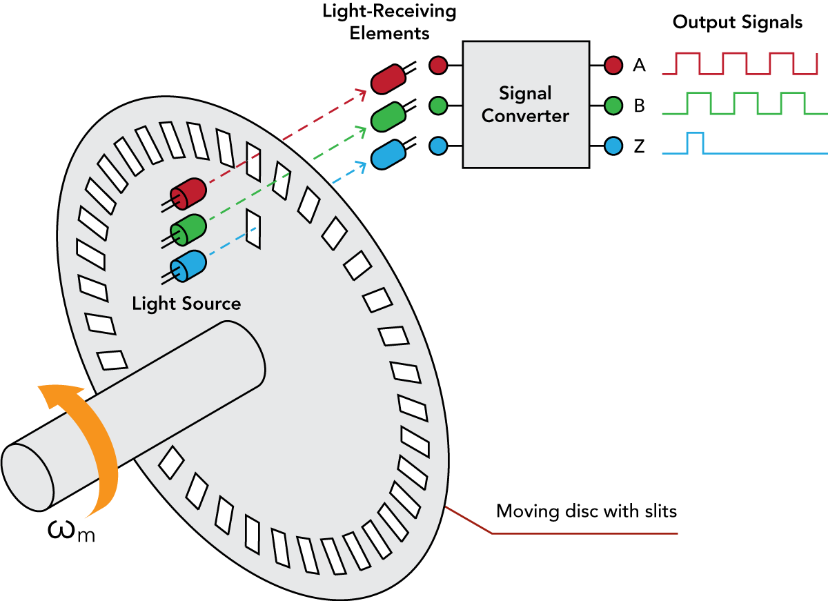
How Incremental Encoders Work
Incremental encoders have two main output signals:
- A (Channel A)
- B (Channel B)
These signals indicate movement and direction when the shaft rotates. Some encoders also include a third signal, Z, which serves as a reference point for position calibration.
Signal Representation
Here is an image illustrating signals A, B, and Z:
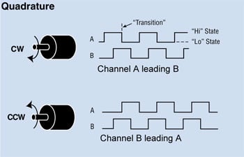
Quadrature Outputs
Incremental encoders employ a quadrature encoder to generate their A and B output signals. The pulses from these outputs are quadrature-encoded, meaning that A and B are phase-shifted by 90 degrees when the encoder moves at a constant speed.
At any given moment, the phase difference between the A and B signals indicates the encoder's rotation direction:
A phase difference of +90° corresponds to clockwise rotation.
A phase difference of −90° corresponds to counterclockwise rotation.
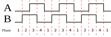
Quadrature Encoding Table
Resolution of an Incremental Encoder
The resolution of an incremental encoder determines its precision. It is specified as:
- Pulses per Revolution (PPR) for rotary encoders.
- Pulses per Unit Distance (e.g., mm) for linear encoders.
Each signal edge (rising and falling transitions of A and B) represents a detected position change. Since each full cycle has four edges (rising A, rising B, falling A, falling B), the measurement resolution is one-fourth of a full A or B output cycle.
For example, a 1000 pulse-per-revolution (PPR) rotary encoder has:
- Per-cycle measurement resolution = 360° / 1000 cycles = 0.36° per pulse
- Effective resolution = 0.36° / 4 = 0.09° per edge
ESP32 Code for Incremental Encoder
Below is a simple ESP32 Arduino code to read an incremental rotary encoder:
#define outputA 17
#define outputB 16

volatile int counter = 0;
volatile int aLastState;

void IRAM_ATTR handleEncoder() {
  int aState = digitalRead(outputA);
  if (aState != aLastState) {
    if (digitalRead(outputB) != aState) {
      counter++;
    } else {
      counter--;
    }
  }
  aLastState = aState;
}

void setup() {
  pinMode(outputA, INPUT);
  pinMode(outputB, INPUT);
  Serial.begin(9600);
  aLastState = digitalRead(outputA);
  attachInterrupt(digitalPinToInterrupt(outputA), handleEncoder, CHANGE);
}

void loop() {
  static int lastCounter = 0;
  if (lastCounter != counter) {
    Serial.print("Position: ");
    Serial.println(counter);
    lastCounter = counter;
  }
}
Why Use an Interrupt Instead of digitalRead in the Loop?
Using an interrupt function (attachInterrupt) allows the microcontroller to immediately detect changes in the encoder signal without continuously checking in the loop(). If we used digitalRead in the loop, we might miss some pulses, especially if the encoder rotates quickly. Interrupts ensure real-time response to changes in the encoder's state, leading to more accurate readings.
Understanding volatile and IRAM_ATTR
volatile: This keyword tells the compiler that a variable can be modified by an interrupt, preventing optimization that might lead to incorrect behavior.IRAM_ATTR: This attribute ensures that the interrupt handler function (handleEncoder) is stored in IRAM (Instruction RAM) for faster execution, which is crucial for real-time processing.
Why Can't We Use Serial.print in handleEncoder?
The handleEncoder function is an Interrupt Service Routine (ISR), which should execute as quickly as possible. Using Serial.print inside an ISR can cause issues because:
- Serial communication is slow compared to ISR execution speed.
- Serial functions use interrupts internally, which may conflict with the encoder ISR.
- Delays in ISR execution can cause missed pulses, leading to inaccurate readings.
Conclusion
Incremental rotary encoders are fundamental in position and motion sensing applications. Understanding how they generate quadrature signals allows precise control and tracking of rotary motion. With an ESP32 and a simple interrupt-driven approach, you can easily integrate an incremental encoder into your projects.