Understanding UART and Serial Communication
2025-02-14
Data Transmission
Data transmission can be categorized into two main types: Serial and Parallel. Serial communication, in particular, has several subtypes, including Asynchronous, Synchronous, and Isochronous. In this post, we’ll focus on UART (Universal Asynchronous Receiver-Transmitter), which is an asynchronous method of communication. Unlike synchronous communication, UART does not require devices to share the same clock cycles or be synchronized.
![]()
Serial vs. Parallel Transmission
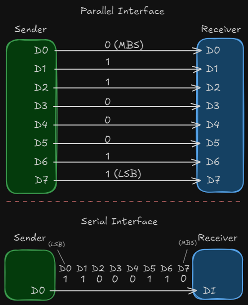
Serial Transmission: Data is sent one bit at a time over a single communication channel. This method is simpler and more cost-effective but can be slower compared to parallel transmission.
Parallel Transmission: Data is sent in groups of 8 bits (a byte) simultaneously over multiple channels. While faster, it is more complex and expensive due to the need for multiple communication lines.
Both methods enable devices to communicate, but they differ in their approach. Serial transmission is often preferred for its simplicity and lower cost, while parallel transmission is used when speed is critical.
Key Terms:
- MSB (Most Significant Bit): The bit with the highest value in a byte (e.g., 2^7).
- LSB (Least Significant Bit): The bit with the lowest value in a byte (e.g., 2^0).
Serial Transmission
In serial transmission, bits are sent one after another over a single communication channel. This reduces the cost of transmission compared to parallel methods, which require multiple channels. Serial transmission can be implemented in three ways: asynchronous, synchronous, and isochronous.
Asynchronous Transmission (UART)
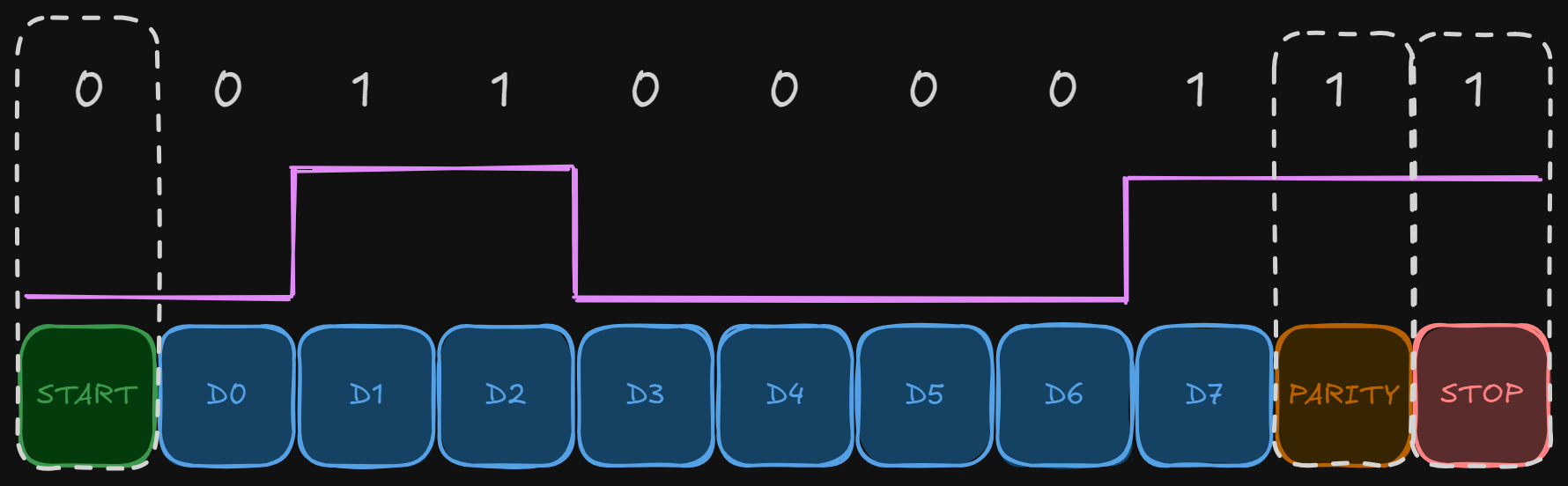
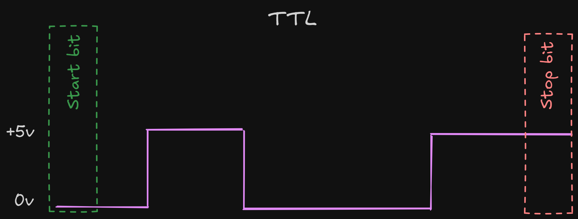
Asynchronous transmission does not rely on a shared clock signal between devices. Instead, it uses agreed-upon patterns to communicate data. Each byte of data is framed with a start bit and one or more stop bits, allowing the receiver to identify the beginning and end of each byte.
- Start Bit: A single bit (usually 0) that signals the start of a byte.
- Stop Bit(s): One or more bits (usually 1s) that signal the end of a byte.
Between bytes, there may be a gap or idle time, which helps the receiver prepare for the next byte. The receiver synchronizes with the incoming data stream at the start of each byte, ensuring accurate data interpretation.
Note: Asynchronous transmission is "asynchronous at the byte level," but the bits within each byte are still synchronized.
UART: Universal Asynchronous Receiver-Transmitter
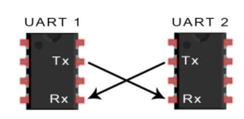
UART is a hardware device that facilitates asynchronous serial communication. It uses two wires:
- Tx (Transmit): Sends data from the transmitting device.
- Rx (Receive): Receives data at the receiving device.
The communication speed, known as the baud rate, must be agreed upon by both devices.
Baud Rate: How It Works
The baud rate is a critical parameter in serial communication, especially in UART. It defines the speed at which data is transmitted and received, measured in bits per second (bps). Here’s how it works:
Definition: The baud rate represents the number of signal changes (symbols) per second. In UART, each symbol typically corresponds to one bit, so the baud rate is often equal to the bit rate.
Synchronization: Both the transmitter and receiver must be configured to use the same baud rate. If they are not synchronized, data will be misinterpreted, leading to communication errors.
Common Baud Rates: Some standard baud rates include 9600, 19200, 38400, 57600, and 115200 bps. Lower baud rates are used for longer distances or noisy environments, while higher baud rates are used for faster communication over shorter distances.
Calculation: The baud rate determines the duration of each bit. For example, at 9600 bps, each bit lasts approximately 104 microseconds (1 second / 9600 bits).
Error Tolerance: The receiver samples the incoming data at the midpoint of each bit. If the baud rates of the transmitter and receiver are slightly mismatched, the sampling point may drift, causing errors. Therefore, precise baud rate configuration is essential.
TTL vs. RS-232
TTL (Transistor-Transistor Logic):
- Operates at 5V.
- Commonly used in short-range communication.
- Not a protocol but refers to the voltage level used by UART.
- Example: USB-to-TTL converters.
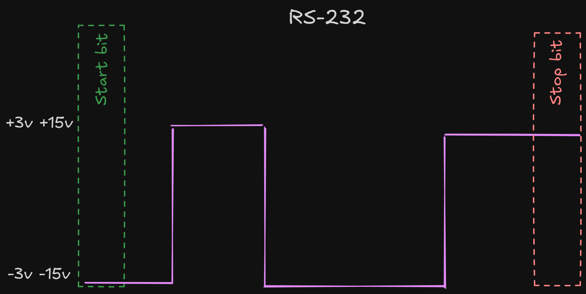
RS-232:
- Uses higher voltage levels (+/- 12V) for long-range communication.
- Voltage levels:
- -3V to -15V represents a "1" bit.
- +3V to +15V represents a "0" bit.
- Active low logic.